title: ESP32-P4-Module High-performance Development Board, Based On ESP32-P4 And ESP32-C6, Supports Wi-Fi 6 And Bluetooth 5/BLE | ESP32-P4-Module-DEV-KIT
source: https://www.waveshare.com/esp32-p4-module-dev-kit.htm?&aff_id=111694
author:
published:
created: 2025-04-09
description: ESP32-P4-Module High-performance Development Board, Based On ESP32-P4 And ESP32-C6, Supports Wi-Fi 6 And Bluetooth 5/BLE | ESP32-P4-Module-DEV-KIT
tags:
  - Hardware
ESP32-P4-Module High-performance Development Board, Based On ESP32-P4 And ESP32-C6, Supports Wi-Fi 6 And Bluetooth 5/BLE | ESP32-P4-Module-DEV-KIT
Details
ESP32-P4-Module High-performance Development Board, Based On ESP32-P4 And ESP32-C6, Supports Wi-Fi 6 And Bluetooth 5/BLEESP32-P4-Module Development Board
High-performance Development Board Based On ESP32-P4 And ESP32-C6
Rich Human-machine Interfaces

 Kit Selection

 Kit Connection Examples
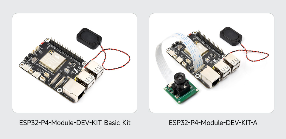


DSI Capacitive Touch Display Comparison
Optional For DSI Capacitive Touch Display, IPS Screen, Optical Bonding Toughened Glass Panel, With 178° Wide Viewing Angle. Supports 10-Point Touch, provides clear image and excellent visual experience

| Model | 7-DSI-TOUCH-A | 10.1-DSI-TOUCH-A |
|---|---|---|
| Resolution | 720 × 1280 (H×V) | 800 × 1280 (H×V) |
| Communication Interface | MIPI 2-lane | |
| Brightness | 450cd/m² (supports customization for 1000cd/m² high brightness version) | 400cd/m² (supports customization for 1000cd/m² high brightness version) |
| Touch Chip | GT9271 | |
| Outline Dimension | 120.24mm × 189.32mm | 147.0mm × 239.0mm |
| Display area | 88.0mm × 155.0mm | 135.96mm × 217.18mm |
| Pixel pitch | 0.12075mm × 0.12075mm | 0.1175mm × 0.1088mm |
| Contrast ratio | 800:1 | |
| Operation temperature | 0℃~60℃ | |
* the DSI LCD is only included in the ESP32-P4-Module-DEV-KIT-B and ESP32-P4-Module-DEV-KIT-C.
Raspberry Pi Camera (B)
5MP | Manual Focus
Compatible with Raspberry Pi series boards

| Sensor | OV5647 | CMOS size | 1/4inch |
|---|---|---|---|
| PIXELS | 5MP | Aperture | F2.0 |
| Focal length | 6mm | Field of view | 60.6° |
| Night Vision function | Not support | FOCUSING | Manual Focus |
Development Board Introduction
This product is a multimedia development board based on ESP32-P4 with integrated ESP32-C6, supports Wi-Fi 6 and Bluetooth 5 wireless connection. It features rich Human-Machine interfaces, including MIPI-CSI (with integrated Image Signal Processor), MIPI-DSI, SPI, I2S, I2C, LED PWM, MCPWM, RMT, ADC, UART, TWAI, etc. Additionally, it supports USB OTG 2.0 HS, onboard RJ45 Ethernet port with reserved PoE function header, and onboard 40PIN GPIO header which is compatible with some Raspberry Pi HATs, enabling a wider range of application adaptability.
The ESP32-P4 adopts a 400MHz dual-core RISC-V processor and supports up to 32MB PSRAM, featuring USB 2.0, MIPI-CSI/DSI, H.264 encoder, and other peripherals, meeting the needs for low-cost, high-performance, and low-power multimedia development. It also integrates the Digital Signature Peripheral and a dedicated Key Management Unit, ensuring secure data and operations. Specifically designed for high-performance and high-security applications, the ESP32-P4-Module-DEV-KIT meets the requirements of Human-Machine interaction, efficient edge computing, and IO expansion.
Key features include:
- High-performance MCU with RISC-V 32-bit dual-core and single-core processors
- 128 KB HP ROM, 16 KB LP ROM, 768 KB HP L2MEM, 32 KB LP SRAM, 8 KB TCM
- Powerful image and voice processing capability. Provides image and voice processing interfaces including JPEG Codec, Pixel Processing Accelerator, Image Signal Processor, H264 encoder
- 32MB PSRAM in the chip's package, with onboard 16MB Nor Flash
- Commonly used peripherals such as MIPI-CSI, MIPI-DSI, USB 2.0 OTG, Ethernet, SDIO 3.0 TF card slot, microphone, speaker header and RTC battery header, etc.
- Adtaping 2*20 GPIO headers with 28 x remaining programmable GPIOs
- Security features: Secure Boot, Flash Encryption, cryptographic accelerators, and TRNG. Additionally, hardware access protection mechanisms help to enable Access Permission Management and Privilege Separation
Highly integrated and powerful performance
Adopts ESP32-P4-Module, with built-in ESP32-C6 and 16MB Nor Flash
 Wi-Fi 6 and Bluetooth support
built-in ESP32-C6 module to extend 2.4GHz Wi-Fi 6 and Bluetooth 5/BLE for ESP32-P4, using SDIO interface protocol for communication, stable connection and efficient transmission.
 Reserved PoE Module Header
More Flexible for Power Supply

* the PoE module is NOT included
Connect to a PoE Module for PoE Power Supply
Provides Both Network Connection And Power Supply for ESP32-P4-Module-DEV-KIT board In Only One Ethernet Cable

* the PoE HAT (F) and the switch in the picture above are NOT included.
What's On Board 
-
ESP32-P4-Module
Built-in ESP32-P4NRW32, ESP32-C6, 16MB Nor Flash -
Display interface
MIPI 2-lane -
Camera interface
MIPI 2-lane -
Type-C UART connector
for power supply, program burning and debugging -
RTC battery header
for connecting rechargeable RTC battery (supports rechargeable RTC batteries only) -
Type-C connector
for power supply and program burning -
I2C header
-
I3C header
-
PoE module header
connect to external PoE module for PoE power supply function -
Onboard microphone
-
Speaker header
MX1.25 2P connector, supports 8Ω 2W speaker -
Type-A Ports
USB OTG 2.0 high-speed ports, switching to HOST or DEVICE via jumper -
USB OTG function selection
switching to HOST end for expanding USB ports -
RJ45 100M Ethernet port
-
40PIN GPIO header
-
ESP32-C6 SMD Antenna
SDIO 3.0 interface protocol, extending Wi-Fi 6 / Bluetooth 5 -
ESP32-C6 UART header
-
5V power header
-
BOOT button
Press it when powering on or resetting to enter download mode -
RST Reset button
-
Power supply indicator
-
TF card slot
SDIO 3.0 interface protocol
Pin definition  outline dimensions
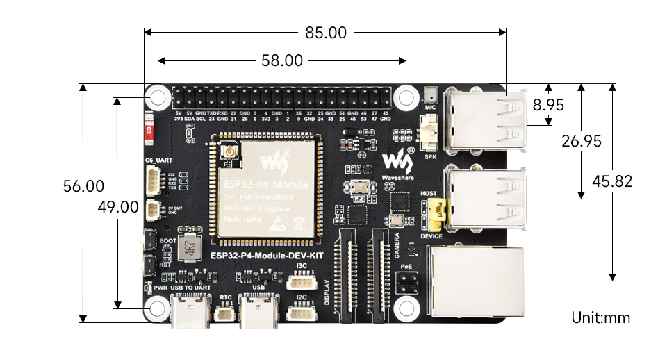
Resources & Services  Wiki: www.waveshare.com/wiki/ESP32-P4-Module-DEV-KIT
Quick Overview
ESP32-P4-Module-DEV-KIT
- ESP32-P4-Module-DEV-KIT x1
- 8Ω 2W speaker x1
1 2
2 


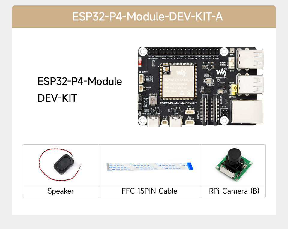
ESP32-P4-Module-DEV-KIT-A
- ESP32-P4-Module-DEV-KIT x1
- 8Ω 2W speaker x1
- FFC 15PIN cable x1
- RPi Camera (B) x1
1 2 3  4
4 


ESP32-P4-Module-DEV-KIT-B
- 7-DSI-TOUCH-A x1
- ESP32-P4-Module-DEV-KIT x1
- Screws pack x1
- USB Type-A dual-plug cable x1
- USB Type-A to Type-C cable x1
- 2PIN cable x1
- DSI cable x1
- FFC 15PIN cable x1
- FFC 22PIN cable (2PCS) x1
- 8Ω 2W speaker x1
- RPi Camera (B) x1

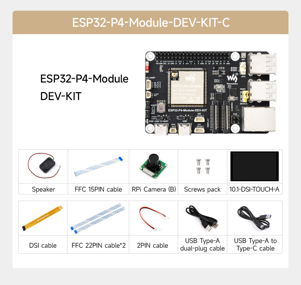
ESP32-P4-Module-DEV-KIT-C
- 10.1-DSI-TOUCH-A x1
- ESP32-P4-Module-DEV-KIT x1
- Screws pack x1
- USB Type-A dual-plug cable x1
- USB Type-A to Type-C cablex1
- 2PIN cable x1
- DSI cable x1
- FFC 15PIN cable x1
- FFC 22PIN cable (2PCS) x1
- 8Ω 2W speaker x1
- RPi Camera (B) x1

ContactLeave a message for us Sorry, we are currently not online. Please leave a message and we will get back to you as soon as possible.